
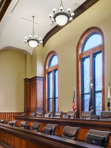
The ambitious restoration plan was well received by the county despite the additional cost, and research into the design and construction of the original courthouse began along with due diligence about existing conditions. These steps proved challenging, however, due to a lack of as-built drawings and documents depicting the original spaces, as well as the difficulties of accessing and visually observing the high spaces above the drywall ceiling on the second floor. The design team had just three historical photos that showed the original interior of the courthouse.
To obtain more detailed information about the original construction and the existing conditions, Dewberry proposed a laser-scanning process that would provide black-and-white, high-definition scans of the entire building from basement to attic. During a four-week timeframe, Valdes Engineering Co., Lombard, Ill., produced detailed scans of the hard-to-view spaces. Because the building remained occupied throughout the project, the scanning work was largely completed after hours.
The laser scanning process created an electronic “map,” modeling the building in a format that could be used in a 3-D environment. The scans, which were performed from multiple locations to capture as much data as possible, were completed with a tripod-mounted phase-based scanner. Once the field scanning had been completed, all the individual scans were registered into one overall laser model, which was then exported to the design software package.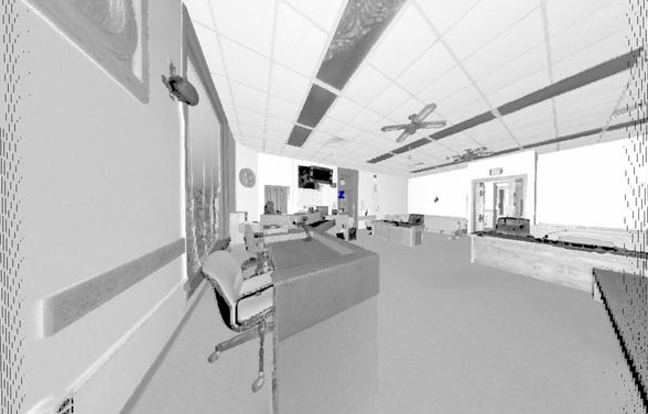
Accurate to one-quarter inch, the scans revealed the condition and location of skylights, wood beams, wood trim around the arched windows and structural elements, as well as the location of piping and conduit. The information proved invaluable to determining the extent of repairs, defining the scope of work and creating accurate cost estimates. Prior to the scanning process, for example, the design team had noticed strange, sloping enclosures in the attic space. Even the maintenance staff was uncertain as to their function. After the scans indicated the outline of what might be an intact skylight, a follow-up investigation revealed the old leaded glass of one of the skylights under dirt and debris. A second skylight was missing and had been covered with wood.
The laser scans also helped to understand exact clearances and spatial dimensions, aiding the installation of the new HVAC system. The building had a unique cross-section and structural system. Using the scans, the team was able to accurately model the large trusses and complex web of other structural components supporting the main tower. The mechanical engineer could then determine the best locations to run ductwork and other systems. Completing this task in a 2-D drawing program would have been extremely difficult.
The scans further helped determine wall thicknesses and general orientation, which would have been impossible with a simple tape measure. The walls were rarely aligned, thickness varied throughout the building and right angles were a rarity. The floors sloped dramatically, especially in the basement, requiring plans to alter or replace certain floors to allow for proper code-compliant egress.
The scans, containing millions of data points, were viewed using Autodesk Navisworks and were used as an overlay to create the BIM model. The scans also allowed for improved constructability reviews early in the process.
Photos unless otherwise noted: Mariusz Mizera